HOT
 Production-Quality Lenses Directly from SLA 3D P…
 Forging Ahead with Solar Energy and GibbsCAM CNC…
 GibbsCAM Software Helps Race-Team Mechanics Beco…
 Metro Aerospace Introduces 3D Printed Part for F…
 GibbsCAM Enables Rover Exploration Vehicle Parts…
 Designing a Custom Boot for an Injured Penguin
 Asano Uses Geomagic 3D Scan Software to Drive In…
Reigniting the F-1 Apollo Engine with Geomagic 3D Scanning Solutions
"It was evident from the start that 3D scanning and imaging were a requirement of this job."

Apollo F1 engine scan into Geomagic
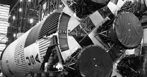
NASA’s most powerful liquid-fuelled rocket, powered by the F-1 engine, was originally used in the Apollo Program between 1967 and 1973, to launch Saturn V rockets into orbit. Now, 40 years later, one of the original engines has been brought out of storage to be adapted for the new Space Launch Systems (SLS) Program.
The Mission:
Although some blueprints of the original F-1 engine design exist, the basic drawings that were available revealed a disconnect between the original design and as-built results. As such, the only way to obtain an accurate design of the F-1 was to map it using 3D tools.
Executing on the Challenge:
With more than 400 major parts to the rocket, not including bolts and fasteners, the team at NASA’s Marshall Space Flight Center, assisted by ShapeFidelity, Inc., an engineering services consultant specializing in 3D scanning and consulting for advanced manufacturing, strategized how best to achieve their goal.
“It was evident from the start that 3D scanning and imaging were a requirement of this job,” stated Rob Black of ShapeFidelity. “While the mission was clear, the magnitude of the project was huge and not easy to estimate. We weren’t sure how many parts were involved, or if it was even possible, and the fear was that once the engine was dismantled, we would have no way to reassemble it.”

Close-up of detailed 3D scan data
3D Scanning and Point Cloud Processing:
Using Geomagic Solutions software for reverse engineering, combined with an ATOS Triple Scan and a TRITOP system for scanning, the team created a baseline scan, or Outer Mold Line (OML) model, of the entire engine. Then they methodically removed each part, scanned them individually, and processed them into accurate 3D data with Geomagic.

3D Inspection of soot on the original turbine blades
The Geomagic Reverse Engineering software allows for fast and accurate cleanup of point cloud data into 3D surface models. Once each part was completed, it was positioned back into the virtual assembly model based on the TRITOP assembly survey. The completed data took 4 months of careful disassembly, scanning and cataloging to create, including the delicate ducts and flow paths, which were especially susceptible to distortion during disassembly.
Mission Accomplished:
By the end of the project, the team had exactly what it hoped for: an accurate definition of the F-1 engine, now in 3D, and ready to be used in CAD for analysis, flow path definition, clearances, and re-creation and manufacture the original parts using new materials.


